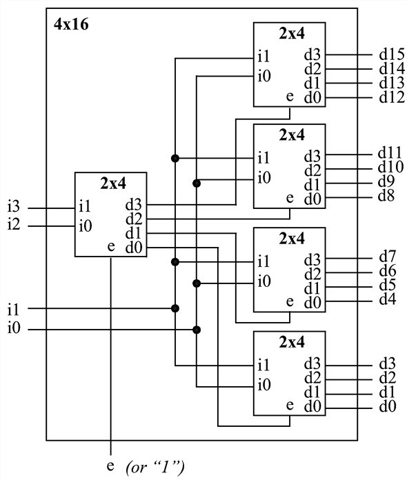
Decoder is a digital circuit that can select a line according to the input pattern. Decoder can be used as a control unit for a MCU,processor etc. 4 to 16 line decoder verilog code arr given bellow.
Verilog Code for 2 to 4 Decoder Behavioral Modelling using Case Statement with Testbench Code. Module 24DEC( input 1:0din, output 3:0dout ); reg 3:0dout. For each case the decoder should output a 16-bit digit with only one of the bits high. I can't manage to get all the desired outputs when I run the program. Jul 15, 2013 Design of Binary to GRAY Code Converter using if-e. Design of 2 to 4 Decoder using CASE Statements (Be. Design of 4 to 2 Encoder using CASE Statements (Be.


4 To 16 Decoder Using 2 To 4 Decoder Verilog Codes
module decoder(x,y,z,w,e,d);
input w,x,y,z,e;
output [15:0]d;
assign d[0]= (~x) & (~y) &(~z) & (~w) & (e) ;
assign d[1]= (~x) & (~y) &(~z) & & (e) ;
assign d[2]= (~x) & (~y) &(z) & (~w) & (e) ;
assign d[3]= (~x) & (~y) &(z) & & (e) ;
assign d[4]= (~x) & (y) &(~z) & (~w) & (e) ;
assign d[5]= (~x) & (y) &(~z) & & (e) ;
assign d[6]= (~x) & (y) &(z) & (~w) & (e) ;
assign d[7]= (~x) & (y) &(z) & & (e) ;
assign d[8]= (x) & (~y) &(~z) & (~w) & (e) ;
assign d[9]= (x) & (~y) &(~z) & & (e) ;
assign d[10]= (x) & (~y) &(z) & (~w) & (e) ;
assign d[11]= (x) & (~y) &(z) & & (e) ;
assign d[12]= (x) & (y) &(~z) & (~w) & (e) ;
assign d[13]= (x) & (y) &(~z) & & (e) ;
assign d[14]= (x) & (y) &(z) & (~w) & (e) ;
assign d[15]= (x) & (y) &(z) & & (e) ;
endmodule
module decoder2();
reg x0,y0,z0,w0,e0;
wire [15:0]dd;

initial
begin
e0=0;
x0=0;
y0=1;
z0=0;
w0=1;
#10 e0=1;
#00 x0=0;
#00 y0=0;
#00 z0=0;
#00 w0=0;
#10 x0=0;
#00 y0=0;
#00 z0=1;
#00 w0=1;
#10 x0=0;
#00 y0=1;
#00 z0=0;
#00 w0=0;
How To Make 4 To 16 Decoder Using 2 To 4 Decoder
#10 e0=0;
end
decoder s(.d(dd),.e(e0),.x(x0),.y(y0),.z(z0),.w(w0));
endmodule